Tim's Modifications to A8 3D Printer
I have only used PLA on my 3D printer and it does what I need, so I see no
reason to change.
Reading about the other types of material to use, most people say that PLA is the easiest to use.
But why modify the 3D printer?
Well, simple answer is: Getting the 1st layer correct.


The 3D Printer I bought
A very nice and cheep kit, I would recommend it to anyone.
I enjoyed assembling it and it prints very well.
So why change a good thing? If it works leave well alone.
Well, when you get the kit, it comes with a layer of masking tape on the bed
ready for a print.
After a few prints this tape starts to become damaged and needs replacing.
With the right type of masking tape, the first layer of your print will
usually work, the tolerance the bed has to be within, can be quite relaxed.
(when I say relaxed, within 0.5mm)
The manufacturers of the kit obviously found the best masking tape for the
job, as the tape that comes on the bed works great, I only wish they had put a
roll of it in the kit.
So finding the right masking tape can get expensive, as not all masking tape
is the same.
After many purchases and an empty wallet, I found the Blue Homebase brand
worked best for me.
Still, why change things?
The trouble I was having, with masking tape, the tack starts to fail when
heated, and you need to heat the bed to stop shrinkage until the print is
done, or the print will curl up at the edges.
So, I thought there must be something better than masking tape, and had
a look on the web.
Yes there is.
But so expensive.
So, I thought what are they making this stuff out of, and is there
something else made of the same stuff but cheaper and can be repurposed.
Yes there is.
Well something similar.
To use it we need to get the printer setup more accurate than it currently
stands.
It's not a problem with the bed, that can be adjusted with the screws.
It's the X and Z supports.

|
These are the original 3D Printed X and Z Supports |
If you examine these two part closely, like me you will probably get the
impression that they are mass produced at the fastest print speed they can get
away with.
As the two parts are different, you will get different amounts of shrinkage.
Not much, but enough to make a difference,
we need accuracy less than 0.2 mm. (The thickness of first layer)

|
Holes where the X axis linier bars go. |
Take a set of Callipers and measure the
distance across the two horizontal bars.


Mine are both exactly the same now, but before I did the new supports there
was a 0.5mm difference.
This may not seem a lot, but you must remember the first layer is only 0.2 mm
thick.
So, how did I get both side exactly the same?
I made both parts that hold the bars, exactly the same.
The differences made as separate items, then screwed together.
Although a 3D printer can do complicated parts in one piece, I have
found it is sometimes not practical to do so. Some parts are better done in
pieces, this not only makes it easier to print some parts, it also enables you
to change individual pieces rather than scrap the whole part.
Having things screwed together also enable you to make tiny adjustment if
things don't line up correctly.
The screws I use are M3 x 10mm Pan Head Flat Tail Self Tapping Sheet Metal
Screw.
The 8mm Linear Motion Ball Bearing that coms with the kit are the 45mm long
ones, one on each.
I had some of the shorter ones 24mm long, so I used 4 of them, 2 on each.
My mod can use the original ones, 2 ridges will need to be removed, easy with
a crafting knife.

|
Remove the 2 inner ridges and place the original Bering at one end |

|
This is what mine look like, notice I have changed the position of the Jack Nut mount. |

|
Here is a screen shot showing all the parts and the orientation to print them. You may wish to print them one item at a time. You need to make a mirror copy of the Jack Nut support. |
I printed these with a top/bottom and shell thickness of 1.6mm
STL Files:
Over time I have made more modifications to the horizontal assembly.
This requires some parts I got from eBay.
GT2 Idler Timing Pulley 16 Tooth 3mm Bore. (Get Two, one for the bed Timing Belt)
I have used the Steel Wire and the Fiberglass Cored Timing Belts.
I found that the Steel Cored belts do not bend around the small Timing Pulleys easily and require too much tension applying to make them do so. I recommend Fiberglass.
GT2 6mm wide Timing Belt (Fiberglass). (get enough to replace the Bed Timing Belt as well)
M3 x 25mm long Stainless Steel Set Screws. ( Three are needed for the tensioner)
M3 Square Stainless Steel Nuts. (Two are needed for the tensioner, I used a self locking nut on the Idler)

Two parts need printing for the Timing Belt Link.
STL Files:

2x Short pieces of Timing Belt cut to 14mm long are needed to lock the Timing
Belt in place.
2x M3 x 5mm long set screws are needed to fasten the Timing Belt Link in
place.
2x M3 x 10mm long self taping screws are needed to affix the Timing Belt
Link Cover.

Place the short pieces of Timing Belt on the ends of the Timing Belt, then
slide the ends into the slots on the Timing Belt Link.
Use the two M3 Set screws to fix the Timing Belt Link in place.
then affix the Timing Belt Link Cover using the self tapping screws.

For the Belt Tensioner, only one piece needs printing.
STL File: Trolley_Timing_Belt_Tentioner.stl

|
The underside will need cleaning of debris, where the square nuts go. |
3x M3 x 25 long Allen Head set screws, one for the Idler and two for setting
tension.
2x Square M3 nuts, for the tension screws.
1x M3 self locking nut, for the idler bolt.
1x GT2 Idler Timing Pulley with 16 Teeth and bearings with 3mm Bore.
2x washers for idler bolt.

Place the two Allen Set Screws and the Square Nuts into the Horizontal Timing
Belt Tensioner.
Have the Set Screws protruding about only 5mm at this time.
Place the Idler in the Timing Belt Ready to be placed in the Timing Belt
Tensioner.


Fit the Horizontal Timing Belt Tensioner on the end of the Horizontal Support,
the two adjusting Set Screws should slide in the end of the Horizontal Support
freely.
Push the Timing Belt with the Timing Belt Idler into the Timing Belt Tensioner
and fit the Timing Belt Idler securing Bolt, fit the Nut. (don't for get the
washers if fitting them)
The nut for the Idler securing bolt does not need to be tight.
Once fitted, make sure the Horizontal Liner Bars are seated all the way into
the Left Hand Horizontal Support. (Looking from the front of the machine)
Then adjust the Adjusting Screws until the belt is at the correct tension.


|
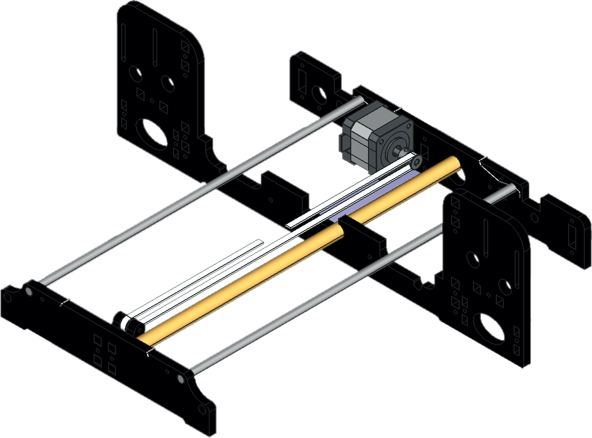
I have done this animated Cutaway Sketch to show that there is no longer any force applied to the Right Hand Horizontal Support due to the tensioning of the Timing Belt.Previously if the Timing Belt was given too much tension, it would caused the Right Hand Horizontal Support to apply a pulling force on the Vertical Linear Bar.Now all the tension force is channelled down the Horizontal Linear Bars. |
There is another modification I did to ensure that the Z axis was where it
should be, was to add a spacer in the flexible joint.

If like mine, you had to fix the link at the very ends of the Stepper Motor
Drive and the Jack Screw, so that the Jack Screw reached through the support
at the top of the printer.
This makes the Flexible Link act like a spring.
We want the joint to flex along it's axis if needed, but we don't want it
bouncing up and down.
(Well, up yes, sort of, if it hits a bit of debris, but when it comes back
down, we want it to come down to the correct position, and not into your
print. )
So, we need to place a spacer inside.
Something about 6mm diameter and 12mm long.

|
| I have drawn a sketch to show what I mean (the spacer is the blue bit). |
When fastening the grub screws on the link, tighten the bottom ones first,
then when you tighten the top ones, just lift the top of the link ever so
slightly before tightening the grub screws.
This will keep a little tension on the spacer inside, and ensure the Jack
Screw is where we want it.

|
RH End Rear View (updated) |

|
RH End Front View (updated) |

|
Motor End Front View |

|
Motor End Back View |
You will see from the front views that I have inverted the Jack Nuts and
placed them at the bottom of the supports.
This means that the screws that locate the Jack screws do not take any weight,
all that the locating screws do, is stop the Jack Nut from rotating.
This means they do not have to be tight, best to leave one slack and the other
just needs tightening so you can move the Jack Nut side to side, but not
vertically.
When these screws are set (ones that go through the brass Jack Nut), slacken
the ones that hold the Jack Nut support to the Main Support on both sides.
Level up both sides to the same height, then tighten them up.
You should find that the Jack Screw moves much more freely through the Jack
Nut now.
For me the Jack Screws where soo free after the mod. They rattled while
printing.
So, I made some anti rattle clips.

|
Clip to stop the annoying rattle while it's printing |
STL File:
Now I can set up my 3D Printer within 0.2mm, it's time for the new bed cover.
NO MORE TAPE.
NO MORE CURLING UP AT THE EDGES.
LOVELY FLAT SMOOTH PRINTS
What is it? I hear you say.
It's simply:
Single Sided Copper Clad Glass Fibre.
Don't get SRPB, that's paper based.
The widest I could find was 200mm.
Length, I got was 300mm and I cut this down to 250mm.
The Thickness of the board I bought was the thicker stuff, 2mm thick. (The
thicker the better I think)
So, I loose 10mm at the front and back, but gain 20mm on the left and 10mm on
the right.

|
I used my plotter I made to score a 10mm grid onto the sheet. I don't think you need to do this, I just had some idea to do it at the time. |
You need to take the glossy shine of the resin before using it.
I did this by rubbing it down with P120 grit wet/dry emery.
Do it wet on a nice flat surface using a block.
Do the whole surface until you see no shiny spots.
When your done and you dry it off make sure you don't touch the surface with your fingers.
The slightest bit of grease, which includes fingerprints will ruin it.
(you can see where I touched it in the photo above)
After rubbing it down and it's dry, take a small stainless steel wire brush and buff it up a little.
Do it so you don't bend the bristles on the brush but do it well. Do it like you would to buff the polish on your shoes :)
Use the brush to remove fingerprints as well.

|
I used double sided adhesive tape to stick it to the bed, didn't use much, just the edges and a bit in the middle. |

|
As mentioned before, it's a little short front and back, but overlaps the bed 20mm on the left and 10mm on the right. |
Copper side is down to the heated bed, fiberglass side is up and is the side
we print on.
Well, lets continue with the improvements.
The Timing Belt fastening under the bed could do with a better fixing.
But before that there is an important thing I must point out for the following
modifications are done.
That is the "H" frame needs to be the correct way up.
I believe the instructions that came with the machine got it wrong, which
ever, for my mods to work correctly, the "H" frame needs the Centre Piece to
be Under the two outer pieces.

|
This way Up, does not alter the position of the Bed, but it does make a difference to the position of the Bed Timing Belt Link. |
Before doing the Bed Timing Belt mod, three parts need printing.
STL Files:

Also required are:
1 GT2 Idler Timing Pulley with 16 Teeth and bearings with 3mm Bore.
1 M3 x 30 long Allen Head set screws, for the Idler. (can use original)
1 M3 self locking nut, for the idler bolt.
2 washers for idler bolt.
4 M3 self tapping screws.
(as used for the Horizontal assembly)
1 M3 x 30 long Allen Head set screws, for the Idler. (can use original)
1 M3 self locking nut, for the idler bolt.
2 washers for idler bolt.
4 M3 self tapping screws.
(as used for the Horizontal assembly)
1 length of 15mm copper pipe, about 370mm long. (that used for plumbing)
New Timing Belt. (if changing)
Now I just have to say, I have see many mods to put tension on the Bed
Timing Belt.
After FOFL I must say from experience, the simple ways are the best.
First thing to do is fit the new Idler.

Next is fit a Restraint.
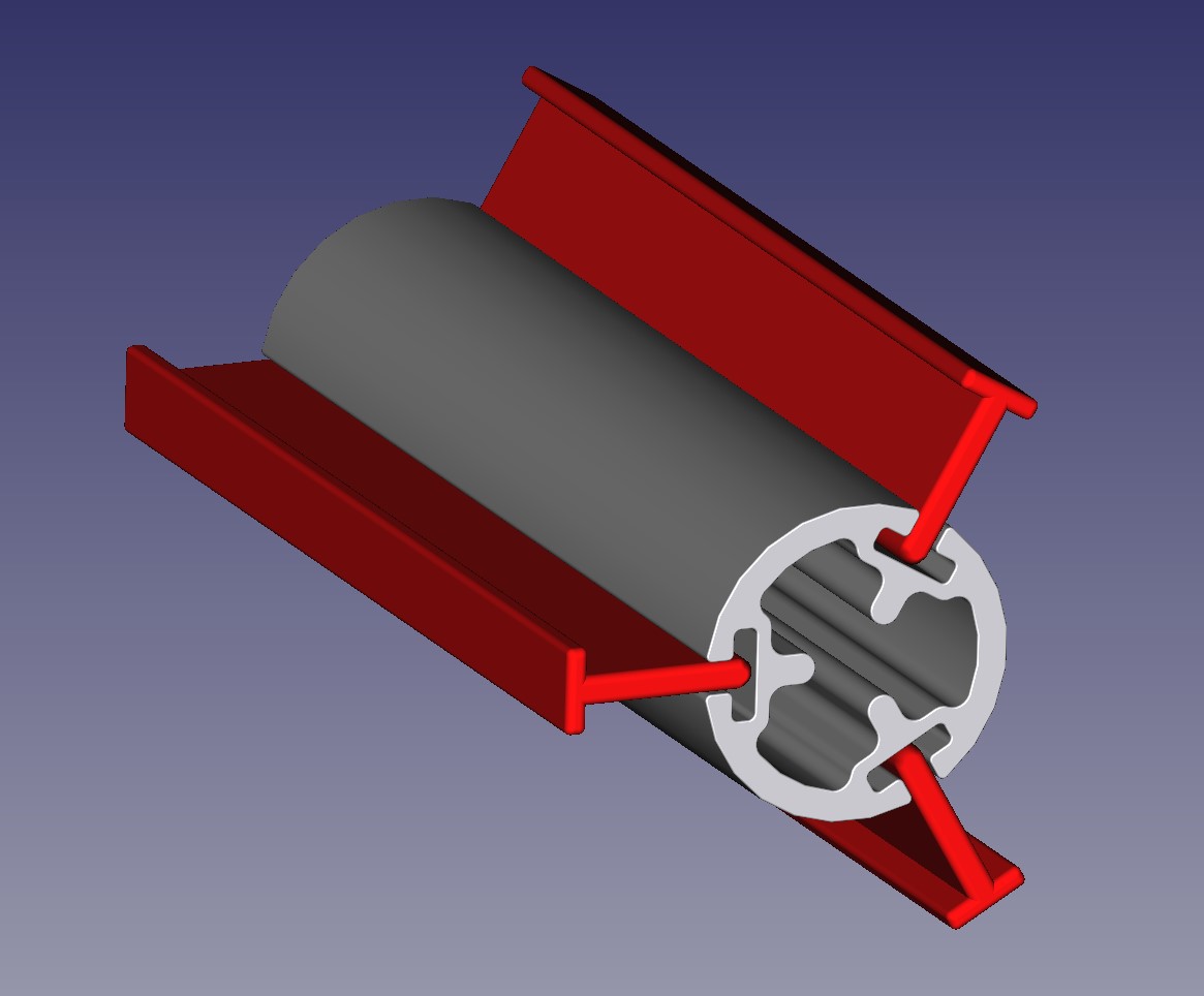
This is I made from 15mm pipe. Any similar item will do, what it needs to do
is keep the Stepper Motor and the Idler apart from each other.
There are two options here:
1. cut a larger hole in the Centre Frame.
2. Cut a notch in the pipe, to fit around the Centre Frame.
I went for option 2, because cutting Perspex usually ends with me breaking it.
The bar needs to be a snug fit. Where the bar hits the Centre Frame, I notched
out about three quarters of it.

With the Idler in its correct position the length of my belt left a gap of
about 40mm.

Next slacken the screws on the Idler mounts as far as they go without them
coming off the nuts.
With the Timing Belt through the Idler connect both ends to the Bed Timing
Belt Link. Inside the Bed Timing Belt Link Clamps I have used short pieces of
Timing Belt to grip the Bed Timing Belt.

Also notice that thickness of the link is different at each end.
The thicker end must end up towards the Stepper Motor.

Connect the Bed Timing Belt Link to the "H" Frame.
Then loop the Timing Belt over the Timing Pinion on the Stepper Motor.
Re-tighten the screws for the Idler Mounts.
(if the belt ends up too tight, slacken off the Idler mounts and adjust the
ends in each Bed Timing Belt Link Clamps)

If done correctly, this should not be need to be done again.
The frame should move freely with minimal effort.
The frame should move freely with minimal effort.
Replace the Bed and level it up.
Settings
I'm only using PLA at the moment.
Bed Temperature:
I have it set at 50 deg. C in Cura.
Don't go below 50 deg. C, if yo do you may find your print will pop off during the print.
Thickness:
Keep the top/bottom and shell thickness down to 1.2mm.
If you want to go thicker, you may need to increase the bed temperature.
Tests

|
The bottom of this screw is only 12mm diameter. |

|
The diameter of the screw at the top is 4mm and is 100mm high. wobbles slightly, but still stuck to the bed. |

|
The screw actually works |
This is just to show how flat and smooth the base of my prints are
now.

|
| After about 50 prints, the double sided tape started to fail. Rather than replace the tape, I have use for the moment, 4 small bulldog clips to hold down the PCB at the edges. |


|
|
Made some clips. (x4) They are 9mm wide |
I didn't want to remove the PCB Bed in case I damaged it while doing so.
So I used my micro pedestal drill I made, to drill the holes and countersink
the holes.

|
|
Using my micro drill without its base to countersink the
holes.
|
|


Did this at all four corners.
Used M3 countersunk x 12mm long set screws, M3 washer and an M3 locknut, to fix them in place.
Used M3 countersunk x 12mm long set screws, M3 washer and an M3 locknut, to fix them in place.
Have printed over 11,500 meters of PLA on this modified bed, and still getting perfectly flat prints without the aide of any platform adhesion type.
The bed is still as good as the day I fitted it.
The photos also show the Adjustment Nut Retainers I made.
Originally the Adjustment Screws went through treaded holes in the "H" Frame and where locked with a Butterfly Nut.
Over time the thread in the aluminium "H" Frame failed, and just the Butterfly Nuts kept the adjustment correct.
This was not an issue if the Butterfly Nut was held when adjusting the Adjustment Screws with a screw driver. But the back ones where difficult to reach.
So I decided to replace the Butterfly nut with Square Nuts and hold the nut from turning with a Retainer.
The Retainer also centralizes the spring.

|
A Cutaway Sketch showing how it fits |

If you take a look at the Heated Bed you will notice that all the Heating Elements are underneath.
So when the Bed is heated, a lot of the heat is lost below it.
(Waste of energy, more load on the heater driver)

The Tray just sits on top of the "H" Frame, but a section of it needs to be razed to allow for the Bed Stepper motor to pass under it.

While on the subject of the bed, I have noticed people think that the MOSFET on the mother board that handles the bed heating element is inadequate, I don't think this is the case.
The reason the MOSFET gets overpowered is: The electrical connection of the plug that connects to the bed is bad.
Because the plug is so close to the bed, over time the heat from the bed expands the electrical socket that connects to the pins of the heater element and causes a loose connection.
Because the bed is constantly moving the loose connection creates power surges.
Eventually the plug or the MOSFET will fail.
For me It was the plug. So I made this simple mod, and have, had no problems since:

Before all this, my 1st mod was to make an extrusion cooler that surrounded
the nozzle, as the one supplied only cooled from one side. I noticed that the
plastic on the far side of the nozzle had a tendency to rise up during the
print.
As I have become better at printing I am now on MK3 nozzle cooler.
I have tried to keep it as small as I can, as I like to be able to see what's
going on.

|
| Sketch I Made to make sure I got it right. |

|
| I used no support when I printed the bottom half, so I guess this print is not for the novice. |
STL Files:
Take Note: This May Not be at
the right height for you. It depends on what distance your nozzle is from the
blower.
Oh you will need 2 screws as mentioned before to put the 2 pieces together.

|
| The Tip of my nozzle is about 25mm from the underside of the frame. |

|
| Fitted |
Oh I forgot there was an other one
before this.
The screw on the top of the extruder was a little painful on the thumb and
fingers.
so I made a button to go over the top of it.

|
| The button makes it easier to press. when changing the filament. |

STL File:

|
| Another mod I made was a guide for the filament, so that the stepper motor for the X axis did not have to keep pulling the filament off the reel. The extruder no longer has any force against it from the filament. |

|
| Here you can see both ends of the guide. It uses Newton's 3rd Law to transfer the force of puling the filament along the pipe and not interfering with the movement of the extruder. |
This enables you place the reel of filament anywhere you like.
I don't think many people will understand what I have done here, but if you
make it the penny will drop and you wonder why it hasn't been done before.

|
| Here's a sketch to show things a little more clearly. |
I have use a length of 4mm OD x 2.6mm ID PTFE tubing to link the two parts.
You will need two lengths (approx. 2x 70mm) of 3mm OD bright polished bar to
support one of the parts at the extruder end.
Also at the extruder end you will need three M4 x 12mm set screws.
At the spool end I have used the self taping screws I mention above.
The reason for the bright bar at the extruder end is to allow for the filament
retraction to happen quickly without any hindrance to the process.

STL Files:
When I printed these out I found that I had made the holes for the pipe a bit
tight.
I had to ream them out with a 5.5mm drill bit.
The pipe can be a slack fit in the fittings.
Don't ream the hole all the way through, the pipe sits on a ledge.
Also the "Extruder End Pipe Support" should be a slack fit on the 3mm bright bar.
The 3mm bright bar should be a tight fit in the "Extruder End Mounting Bracket".
The video shows how smoothly the filament comes off the reel, and the
retraction mechanism in action.
I had to ream them out with a 5.5mm drill bit.
The pipe can be a slack fit in the fittings.
Don't ream the hole all the way through, the pipe sits on a ledge.
Also the "Extruder End Pipe Support" should be a slack fit on the 3mm bright bar.
The 3mm bright bar should be a tight fit in the "Extruder End Mounting Bracket".
Done a new video to try and explain the advantages of this
modification.
Shows that Brittle PLA can be used to print with.

|
| The essential Power Switch. Far better than pulling the plug in and out. |


STL Files:
Power Switch Housing
I also noticed movement in the bars that support the bed.
You can move these up and down slightly, which alters the gap between the bed and the head.
To over come this problem I made 4 simple springs that hold the bars in the lower position.
I made the springs out of 1.2mm dia. spring steel.

|
| I made 2 as draw and 2 opposite hand. |

|
| 1 added at each end of each bar |
This is not a mod but you may find it useful.
When I am adjusting the bed level with my screwdriver.
I thought it would be useful to know by how much I have moved the bed.
So I made this little gadget that attaches to my screwdriver.
The bed is secured in place with
standard M3 set screws.
The standard M3 screw has a thread pitch of 0.5mm.
Therefore if you have something that can indicate you have rotated you
screwdriver 1/5th of a turn, then you know you have moved the bed 0.1mm.
Remember though: you are only moving one corner at a time, so you have to
incorporate the principles of leverage. (moving 1 screw 0.2mm on one corner
may only move the middle 0.1mm)

|
It's a Pentagon shaped ring that slides over the shaft over my screwdriver.(5 sides) |
Extruder Cooler Mod
Sometimes I have had a little difficulty changing the filament.
Some times a bit of the previous filament gets left in the top of the feed
pipe and I have had to strip down the fan to get access and remove the
obstruction.
So I have come up with this little mod so that I have access all the time.

|
Front View |

|
| Back View |

|
| Here's a sketch to show it a little clearer |
It was quite cheep to make, I only had to by 2 pieces.
First the heat transfer pipe and fins.
search eBay for:

Second was a Spacer to go between the Feeder and the Heatsink.
I shopped around for a piece of aluminium block to do the job, but the price I
thought was too much.
so like always I looked for other cheaper stuff I can re-purpose.
search eBay for:


|
|
I removed the tags, filed down the studs and cut off the top
flange of the Heatsink, also filed 2 notches for the bolt to
pass through.
I cut the Extruder Block in half.
|
You will also need a clamp piece about 6mm thick. (shown in sketch)
I made this from something I had laying around.
It needs to be a minimum of 6mm so that you can use the original bolts, if the
clamp is thinner then you will need washers to make the right overall
thickness.
I put heat transfer paste between all pieces.

STL Files:
You will need longer screws than I normally use to mount the fan if you attach
the guard.
I thought it was time to make a descent Reel Spindle.

There are many different sized 1kg spools, filament is supplied on.
In general the over all size of the spool are pretty much the same,
approximately 200mm diameter by 70mm wide.
But the centre hole for the spindle varies quite a bit.
Currently I have had: 30mm, 50mm, 57mm and 75mm diameter holes in the centre
of the spools.
|
| Here is a sketch of what I made. |
It has a main centre piece and a selection of fins that attach to it depending
on what size the hole in the centre of the spool is.
The centre piece fits over the threaded bar (M8) that came with the printer.
It supports spools with the 30mm hole without any fins attached.
I have made 3 set of fins so far for the other sizes I have had.

STL Files:
I needed somewhere to keep the Fins I was not using so I made a Tray to store
them under the Filament Spool.

It fits neatly in the bottom of the Spool Holder

Vertical Limit Switch Mod
I was not sure whether to post this mod, as it involves some wiring
modifications that are plugged into the Controller Board.
If done wrong Could damage your printer.
So, only do if you know what you are doing and understand the
circuit.
Also setting up and levelling the bed is a little different.


There are many Optical Sensors on the market, I found this one:

Search eBay for:
Optical End Stop Switch
You could use the cables that come with it, but I prefer colour coded wires.
Also two XH2.54 3 pin plugs are needed.
search eBay for:

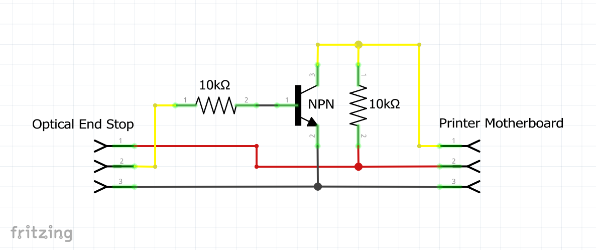
There is a problem with these Optical End Stops, which is: that the signal
wire is on when we need it off, and off when we need it on.
Therefore we need to invert the signal.
To do this I have placed a transistor and a couple of resistors in the circuit
of the cables.
(Any general purpose NPN Transistor should do)

When I received the cables, the colour configuration was not as I needed, it
is necessary to rearrange the order of the cable in the plugs.
Using a pointed tool it is possible to bend down the barbs on the terminals in
the plug housing and remove the cable from the plug housing.

Once the cables have been removed, the barbs need to be bent back so they will
work again.
Then relocate the cables in the correct orientation.
Note! The plugs have wires in different configurations.


Remember to add some shrink-wrap to the cables before soldering all the
joints, so that all connections can be insulated.
Next step is the printed parts.
I have had to redesign the Stepper Motor Bracket to include Holes to screw the
Shutter to it.


STL Files:
The area of the Shutter that passes through the Optical Sensor needs to be
coated with a none transparent coating. (Not transparent to Infrared)
Paint or Nail Varnish may do, I used a Black Permanent Marker.
PLA is quite transparent to Infrared and the Optical sensor uses Infrared.
I have done a video to show this:
To fit the Optical Stop Bracket to the printer two M3 x 25 set screws and two
M3 square nuts are needed.
When setting up and levelling the bed.
If using a 0.1mm sheet of paper as a feeler gauge. It is no longer done when
the head is set to Z home position.
You will need to move the head Z position to 0.1mm above home position.
This can be done from the main Menu.
First Home all
Then from the Main Menu chose => Position.

Then choose => Z Position

This next screen should show:
Z: 0.00mm and Min Endstop:On

Adjust Z to 0.10mm
Min Endstop should switch to Off.

Now turn off the Stepper Motors so that you can adjust the bed.
What I tend to do after adjusting the bed as above, is: to periodically after
a print, measure the skirt it puts down before it prints and adjust the bed
using the Pentagon ring on my screwdriver as shown above. I find this get the
best results.

Any reading between 0.1mm and 0.2mm is good for me.
Also looking at the underside of a print gives you an indication if adjustment
is required.
I thought I should do the Benchy.
(Thought I would use up some old brittle plastic)


(Thought I would use up some old brittle plastic)


I found the perfect companion for my 3D Printer at
Argos.

It's the perfect size, has wheels so you can move it as and when you need it.
Argos product code:
617/2413
Also, I started this blog just after getting my printer, and as usual better
ideas and solutions arise,
so I will update what I change or add.
If you found something useful in this blog you may want to check for any changes now and then.
Happy printing.
Please leave a comment if you have found it useful or want to ask a question.
Tim
so I will update what I change or add.
If you found something useful in this blog you may want to check for any changes now and then.
Happy printing.
Please leave a comment if you have found it useful or want to ask a question.
Tim
I have a web site as well: Tim's Place
best 3d printer under 1000
ReplyDeleteGreat content superb writting style best wishes fom Qidi x-smart review
ReplyDeleteAwesome style keep up blogging.
ReplyDeletehttp://bimforum.co.uk/3d-printing-not-just-for-professionals-must-read/
Tim,
ReplyDeleteThank you for sharig your expertise and your Mods to your Anet A8. Your publishing style is very articulate, making it very easy to follow your thought process. I recently built my first 3-D printer, and I'm discovering just how very important these kind of mods are, to maximizing on the performance capabilities of this printing unit! I'm thoroughly enthused to be able to make the enhancements to mine. I may need to start out with PLA, as I began with ABS, and printing the parts to make the mods has been my most pressing challenge. I made a commitment to myself though, when I first began this journey of discovery into the world of 3D printing, that I would treat the entire process as an exercise in learning, and to therefore, enjoy each nuance along the journey, and the discoveries that I experience, that enrich my understanding and empower me to be a better consultant to others breaking into this evolving technology. I look forward to the opportunity to learn from individuals like yourself, posessing the practical knowledge, and able and willing to share it in a very effective manner as it relates to my personal learning style. (I'm a very visual learner, and the pictures included in your tutorials help me tremendously!) I will follow you with interest and enthusiasm. Again, you have my respect and my gratitude! Respectfully, Dan Kunz - Kunz Kustoms
Thankyou Arthur for leaving a reply.
DeleteI am glad this was of help to you.
I understand PLA is the easiest plastic to use, I have had no reason to change, but I do know if you are going to make something that will end up in direct sunlight where it will get warm, (like in a car) it may distort. So if this is the type of print you need, then ABS once you have mastered PLA.
I have found the key part to making any print is the first layer.
I have seen a lot of mods out there that I feel are not necessary and are done for the wrong reasons.
There is one more mod I have done which I still need to add to the blog, which is the vertical limit switch. I have changed this mechanical switch to an optical one. It makes thing more accurate. (the mechanical switch has different open and closed positions)
some ppl recommend a ball from a ball bearing inside of the flexible coupler so the coupler does not flex up/down 6mm ball...
ReplyDeletehaha, I originally wrote ball bearing (you will need 2 6mm each side), then edited it to what it is."Something about 6mm diameter and 12mm long"
DeleteI assumed that people would use what they have to hand.
Thankyou for leaving a comment.
I suppose you where just being pragmatic, hehe.
Hi, does the "Copper Clad Plate laminate PCB Board Glass Fibre" have to be single or double sided. If single, is it copper side up?
ReplyDeleteThanks
P.S. Wonderful site!
It is single sided copper clad fiberglass (PCB).
DeleteIt is the Fiberglass side that we print on.
I thought the pictures made it clear, but I have edited anyways to make it more clear.
Thanks for leaving a comment, it's good to have feedback about instructions. having done something, one sometimes forget to mention the finer details.
If find something else, that you find unclear, let me know.